Definitions
A rectifier is an electrical device, mainly consists of diodes, that converts alternating current to direct current or at least to current with only positive value, a process known as rectification.
A diode bridge or bridge rectifier is an arrangement of four diodes connected in a bridge circuit, that provides the same polarity of output voltage for any polarity of the input voltage.
Topics of Interest
See also Diodes
A rectifier is an electrical device that converts alternating current to direct current or at least to current with only positive value, a process known as rectification. Rectifiers are used as components of power supplies and as detectors of radio signals. Rectifiers may be made of solid state diodes, vacuum tube diodes, mercury arc valves, and other components.
A circuit which performs the opposite function (converting DC to AC) is known as an inverter.
When only one diode is used to rectify AC (by blocking the negative or positive portion of the waveform), the difference between the term diode and the term rectifier is merely one of usage, i.e., the term rectifier describes a diode
that is being used to convert AC to DC. Almost all rectifiers comprise
a number of diodes in a specific arrangement for more efficiently
converting AC to DC than is possible with only one diode. Before the
development of silicon semiconductor rectifiers, vacuum tube diodes and copper(I) oxide or selenium rectifier stacks were used.
Early radio receivers, called crystal radios, used a "cat's whisker" of fine wire pressing on a crystal of galena (lead sulfide) to serve as a point-contact rectifier or "crystal detector". In gas heating systems flame rectification
can be used to detect a flame. Two metal electrodes in the outer layer
of the flame provide a current path and rectification of an applied
alternating voltage, but only while the flame is present.
Half-wave rectification
A half wave rectifier is a special case of a clipper.
In half wave rectification, either the positive or negative half of the
AC wave is passed easily, while the other half is blocked, depending on
the polarity of the rectifier. Because only one half of the input
waveform reaches the output, it is very inefficient if used for power
transfer. Half-wave rectification can be achieved with a single diode
in a one phase supply.

Full-wave rectification
Full-wave rectification converts both polarities of the input
waveform to DC(direct current), and is more efficient. However, in a
circuit with a non-center tapped
transformer, four diodes are required instead of the one needed for
half-wave rectification. This is due to each output polarity requiring
two rectifiers each, for example, one for when AC terminal 'X' is
positive and one for when AC terminal 'Y' is positive. The other DC
output requires exactly the same, resulting in four individual
junctions (See semiconductors, diode). Four rectifiers arranged this way are called a diode bridge or bridge rectifier:
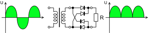
A full-wave rectifier converts the whole of the input waveform to
one of constant polarity (positive or negative) at its output by
reversing the negative (or positive) portions of the alternating
current waveform. The positive (or negative) portions thus combine with
the reversed negative (or positive) portions to produce an entirely
positive (or negative) voltage/current waveform.
Peak loss
An aspect of most rectification is a loss from peak input voltage to the peak output voltage, caused by the threshold voltage of the diodes (around 0.7 V for ordinary silicon p-n-junction diodes and 0.1 V for Schottky diodes).
Half-wave rectification and full-wave rectification using two separate
secondaries will have a peak voltage loss of one diode drop. Bridge
rectification will have a loss of two diode drops. This may represent
significant power loss in very low voltage supplies. In addition, the
diodes will not conduct below this voltage, so the circuit is only
passing current through for a portion of each half-cycle, causing short
segments of zero voltage to appear between each "hump".
Rectifier output smoothing
While half- and full-wave rectification suffice to deliver a form of
DC output, neither produces constant-voltage DC. In order to produce
steady DC from a rectified AC supply, a smoothing circuit, sometimes
called a filter, is required. In its simplest form this can be what is known as a reservoir capacitor, Filter capacitor or smoothing capacitor, placed at the DC output of the rectifier. There will still remain an amount of AC ripple voltage where the voltage is not completely smoothed.
Sizing of the capacitor represents a tradeoff. For a given load, a
larger capacitor will reduce ripple but will cost more and will create
higher peak currents in the transformer secondary and in the supply
feeding it. In extreme cases where many rectifiers are loaded onto a
power distribution circuit, it may prove difficult for the power
distribution authority to maintain a correctly shaped sinusoidal
voltage curve.
For a given tolerable ripple the required capacitor size is
proportional to the load current and inversely proportional to the
supply frequency and the number of output peaks of the rectifier per
input cycle. The load current and the supply frequency are generally
outside the control of the designer of the rectifier system but the
number of peaks per input cycle can be affected by the choice of
rectifier design.
A half-wave rectifier will only give one peak per cycle and for this
and other reasons is only used in very small power supplies. A full
wave rectifier achieves two peaks per cycle and this is the best that
can be done with single-phase input. For three-phase inputs a
three-phase bridge will give six peaks per cycle and even higher
numbers of peaks can be achieved by using transformer networks placed
before the rectifier to convert to a higher phase order.
To further reduce this ripple, a capacitor-input filter can be used. This complements the reservoir capacitor with a choke and a second filter capacitor, so that a steadier DC output can be obtained across the terminals of the filter capacitor. The choke presents a high impedance to the ripple current.
If the DC load is very demanding of a smooth supply voltage, a voltage regulator
will be used either instead of or in addition to the capacitor-input
filter, both to remove the last of the ripple and to deal with
variations in supply and load characteristics.
Voltage-doubling rectifiers
The simple half wave rectifier can be built in two versions with the
diode pointing in opposite directions, one version connects the
negative terminal of the output direct to the AC supply and the other
connects the positive terminal of the output direct to the AC supply.By
combining both of these with separate output smoothing it is possible
to get an output voltage of nearly double the peak AC input voltage.
This also provides a tap in the middle which allows use of such a
circuit as a split rail supply.
A variant of this is to use two capacitors in series for the output
smoothing on a bridge rectifier then place a switch between the
midpoint of those capacitors and one of the AC input terminals. With
the switch open this circuit will act like a normal bridge rectifier
with it closed it will act like a voltage doubling rectifier. In other
words this makes it easy to derive a voltage of roughly 320V (+/-
around 15%) DC from any mains supply in the world, this can then be fed
into a relatively simple switched mode power supply.
Applications
The primary application of rectifiers is to derive usable DC power
from an AC supply. Virtually all electronics except simple motor
circuits such as fans require a DC supply but mains power is AC so
rectifiers find uses inside the power supplies of virtually all
electronic equipment.
Converting DC voltage from one level to another is much more
complicated. One method of such DC-to-DC conversion is to first convert
to AC (using a device called an inverter), then use a transformer to change the voltage, and finally rectify it back to DC.
Rectifiers also find a use in detection of amplitude modulated
radio signals. The signal may or may not be amplified before detection
but if unamplified a very low voltage drop diode must be used. When
using a rectifier for demodulation the capacitor and load resistance
must be carefully matched. Too low a capacitance will result in the
high frequency carrier passing to the output and too high will result
in the capacitor just charging and staying charged.
Rectifiers are also used to supply polarised voltage for welding. In such circuits control of the output current is required and this is sometimes achieved by replacing some of the diodes in bridge rectifier with thyristors, whose voltage ouput can be regulated by means of phase fired controllers.
High-power rectification
Vacuum tubes, metal oxide rectifier stacks and semiconductor diodes
are useful in the range of milliamperes to several thousand amperes of
current in a single device.
Some interesting electromechanical solutions have been devised and
were used before the advent of electron devices. For example, to
convert AC current into DC current in electric locomotives, a synchronous rectifier
may be used. It consists of a synchronous motor driving a set of
heavy-duty electrical contacts. The motor spins in time with the AC
frequency and periodically reverses the connections to the load just
when the sinusoidal current goes through a zero-crossing. The contacts
do not have to switch a large current, but they need to be able to carry a large current to supply the locomotive's DC traction motors. In the past, the vibrators used in battery-to-high-voltage-DC power supplies often contained a second set of contacts that performed synchronous mechanical rectification of the stepped-up voltage.
In recent years semiconductor synchronous rectifiers have been designed; using MOSFET
transistors, they can also rectify with a very low forward voltage drop
and have the additional advantage of being able to switch at extremely
high speeds. Semiconductor synchronous rectifiers are now widely used
in those electronic power supply
units designed for very low output voltages (where the voltage drop in
an ordinary rectifier would represent an unacceptable fraction of the
total output voltage).
Another type of rectifier used in high-voltage direct current power transmission systems and industrial processing between about 1909 to 1975 is a mercury arc rectifier or mercury arc valve. The device is enclosed in a bulbous glass vessel or large metal tub. One electrode, the cathode, is submerged in a pool of liquid mercury at the bottom of the vessel and one or more high purity graphite electrodes, called anodes,
are suspended above the pool. There may be several auxiliary electrodes
to aid in starting and maintaining the arc. When an electric arc is
established between the cathode pool and suspended anodes, a stream of
electrons flows from the cathode to the anodes through the ionized
mercury, but not the other way. These devices can be used at power
levels of hundreds of kilowatts, and may be built to handle one to six
phases of AC current. Mercury arc rectifiers have largely been replaced
by silicon semiconductor rectifiers from the mid 1970s onward. The most
powerful mercury arc rectifiers ever built were installed in the Manitoba Hydro Nelson River Bipole HVDC project, with a combined rating of more than one million kilowatts and 450,000 volts.
The General Electric
Tungar rectifier was an argon gas-filled electron tube device with a
tungsten filament cathode and a carbon button anode. It was useful for
battery chargers and similar applications from the 1920's until
low-cost solid state rectifiers supplanted it. These were made up to a
few hundred volts and a few amperes rating, and in some sizes strongly
resembled an incandescent lamp with an additional electrode.
Another type of rectifier, a motor-generator set or the similar rotary converter, is not a rectifier in the strict sense. Here, an AC motor is mechanically coupled to a DC generator. The DC generator produces a multiphase alternating current in its windings, but a commutator is used to convert the alternating currents into a direct current output; or a homopolar generator
directly produces direct current without need for a commutator. Such
devices are useful for producing thousands of amperes of direct current
at tens to hundreds of volts.
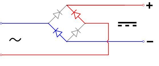
Diode Bridge Operation
A diode bridge or bridge rectifier is an arrangement of four diodes connected in a bridge circuit,
that provides the same polarity of output voltage for any polarity of
the input voltage. When used in its most common application, for
conversion of alternating current (AC) input into direct current (DC) output, it is known as a bridge rectifier. The bridge recitifier provides full wave rectification from a two wire AC input (saving the cost of a center tapped
transformer) but has two diode drops rather than one reducing
efficiency over a center tap based design for the same output voltage.
The essential feature of this arrangement is that for both polarities of the voltage at the bridge input, the polarity of the output is constant.
The diode bridge circuit is also known as the Graetz circuit after its inventor, the physicist Leo Graetz.
Basic operation
When the input connected at the left corner of the diamond is
positive with respect to the one connected at the right hand corner, current flows to the right along the upper colored path to the output, and returns to the input supply via the lower one.

When the right hand corner is positive relative to the left hand
corner, current flows along the upper colored path and returns to the
supply via the lower colored path.

AC, half-wave and full wave rectified signals
In each case, the upper right output remains positive with respect
to the lower right one. Since this is true whether the input is AC or
DC, this circuit not only produces DC power when supplied with AC
power: it also can provide what is sometimes called "reverse polarity
protection". That is, it permits normal functioning when batteries
are installed backwards or DC input-power supply wiring "has its wires
crossed" (and protects the circuitry it powers against damage that
might occur without this circuit in place).
Prior to availability of integrated electronics, such a bridge
rectifier was always constructed from discrete components. Since about
1950, a single four-terminal component containing the four diodes
connected in the bridge configuration became a standard commercial
component and is now available with various voltage and current ratings.
Output smoothing
For many applications, especially with single phase AC where the
full-wave bridge serves to convert an AC input into a DC output, the
addition of a capacitor
may be important because the bridge alone supplies an output voltage of
fixed polarity but pulsating magnitude (see diagram above).

The function of this capacitor, known as a 'smoothing capacitor' (see also filter capacitor)
is to lessen the variation in (or 'smooth') the raw output voltage
waveform from the bridge. One explanation of 'smoothing' is that the
capacitor provides a low impedance path to the AC component of the
output, reducing the AC voltage across, and AC current through, the
resistive load. In less technical terms, any drop in the output voltage
and current of the bridge tends to be cancelled by loss of charge in
the capacitor. This charge flows out as additional current through the
load. Thus the change of load current and voltage is reduced relative
to what would occur without the capacitor. Increases of voltage
correspondingly store excess charge in the capacitor, thus moderating
the change in output voltage / current. Also see rectifier output smoothing.
The simplified circuit shown has a well deserved reputation for
being dangerous, because, in some applications, the capacitor can
retain a lethal charge after the AC power source is removed. A practical circuit should always
include an assured way to safely discharge the capacitor. If the normal
load can not be guaranteed to perform this function, perhaps because it
can be disconnected, the circuit should include a so-called bleeder
resistor connected as close as practical across the capacitor. Because
a bleeder sets a minimum current drain, the regulation of the circuit,
defined as percentage voltage change from minimum to maximum load, is
improved.
The capacitor and the load resistance have a typical time constant τ = RC where C and R
are the capacitance and load resistance respectively. As long as the
load resistor is large enough so that this time constant is much longer
than the time of one ripple cycle, the above configuration will produce
a well smoothed DC voltage across the load resistance. In some designs,
a series resistor at the load side of the capacitor is added. The
smoothing can then be improved by adding additional stages of
capacitor–resistor pairs, often done only for sub-supplies to critical
high-gain circuits that tend to be sensitive to supply voltage noise.
The idealized waveforms shown above are seen for both voltage and
current when the load on the bridge is resistive. When the load
includes a smoothing capacitor, both the voltage and the current
waveforms will be greatly changed. While the voltage is smoothed, as
described above, current will flow through the bridge only during the
time when the input voltage is greater than the capacitor voltage. For
example, if the load draws an average current of n Amps, and the diodes
conduct for 10% of the time, the average diode current during
conduction must be 10n Amps. This non-sinusoidal current leads to
harmonic distortion and a poor power factor in the AC supply.
In a practical circuit, when a capacitor is directly connected to
the output of a bridge, the bridge diodes must be sized to withstand
the current surge that occurs when the power is turned on at the peak
of the AC voltage and the capacitor is fully discharged. Sometimes a
small series resistor is included before the capacitor to limit this
current.
Output can also be smoothed using a choke, a coil of conductor enclosed by an iron frame (similar to a transformer
in construction). This tends to keep the current (rather than the
voltage) constant. Due to the relatively high cost of an effective
choke compared to a resistor and capacitor this is not employed in
modern equipment. Some early console radios created the speaker's
constant field with the current from the high voltage ("B +") power
supply, which was then routed to the consuming circuits, rather than
using a permanent magnet to create the speaker's constant magnetic
field. The speaker field coil thus acted as a choke.
Source: Wikipedia (All text is available under the terms of the GNU Free Documentation License and Creative Commons Attribution-ShareAlike License.)
|


